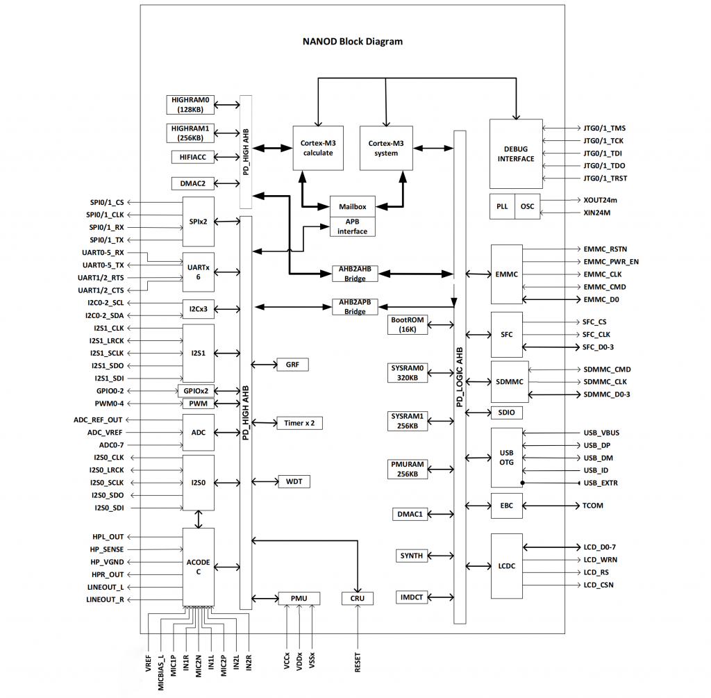
RKNanoD是一款基于ARM Cortex-M3的MCU,用于无线音频、MP3播放器和物联网应用。RKNanoD包括两个M3内核、高达1M字节的Ram、内部电源管理单元、高质量音频编解码器、专用硬件MP3解码加速器、硬件无损音频解码加速器和丰富的外围接口。RKNanoD无需外部存储器即可支持Wi-Fi和蓝牙协议,支持24位192k Hz采样率低功耗无损音频解码,支持三种电源模式。

1.2 Features
The features listed below which may or may not be present in actual product, may be subject to the third party licensing requirements. Please contact Rockchip for actual product feature configurations and licensing requirements.
1.2.1 Boot Option
Boot from eMMC flash
Boot from SPI Nand/Nor flash
Boot from USB
1.2.2 Memory Organization
16KB boot ROM
64KB PMU SRAM for low power sleep mode
320KB SYSRAM0 and 256KB SYSRAM1
128KB HIGHRAM0 and 256KB HIGHRAM1
64KB/bank clock-gate control for reduce power consumption
1.2.3 Processor
Dual ARM Cortex-M3 core
A Thumb instruction set subset
Banked Stack Pointer (SP) only
Hardware divide instructions, SDIV and UDIV (Thumb 32-bit instructions)
Handler and Thread modes
Thumb and Debug states
Interruptible-continued LDM/STM, PUSH/POP for low interrupt latency
Automatic processor state saving and restoration for low latency Interrupt Service
Routine (ISR) entry and exit
Support for ARMv6 unaligned accesses
Nested Vectored Interrupt Controller (NVIC)
32-level priority of interrupt
Dynamic reprioritization of interrupts
Priority grouping. This enables selection of pre-empting interrupt levelsand non
pre-empting interrupt levels
Support for tail-chaining and late arrival of interrupts. This enablesback-to-back interrupt processing without the overhead of state saving andrestoration between interrupts
Processor state automatically saved on interrupt entry, and restored oninterrupt exit, with no instruction overhead.
Mail box
Support dual-core system: system core and calculation core
Support APB interface
Support four mailbox elements, each element includes one data word, one command word register and one flag bit that can represent one interrupt
RKNanoD Datasheet Rev 1.7
Four interrupts to system core
Four interrupts to calculation core
1.2.4 Power Management Unit
Multiple configurable work modes to save power by different frequency or automatically clock gating control or power domain on/off control
2 voltage domains and 3 separate power domains, which can be power up/down by software based on different application scenes
1.2.5 CRU (clock & reset unit)
Support clock gating control for individual components
One oscillator with 24MHz clock input and 1 embedded general purpose PLL
Support global soft-reset control for whole SOC, also individual soft-reset for every components
1.2.6 Hardware Accelerator for MP3 decode
MP3 imdct36 calculation module
MP3 sub-band synthesize module
1.2.7 Watch Dog
32 bits WDT counter width
Counter counts down from a preset value to 0 to indicate the occurrence of a timeout
WDT can perform two types of operations when timeout occurs:
Generate a system reset
First generate an interrupt and if this is not cleared by the service routine by the time a second timeout occurs then generate a system reset
Programmable reset pulse length
Total 16 defined-ranges of main timeout period
1.2.8 Memory Interface
SD/MMC controller
SD/MMC SPI mode/1bit mode/4bit mode
Support Multi Media Card Specification Version 4.41
Support SD Memory Card Specification Version 2.0
Cards Clock Rate up to PCLK, Re-scaling the SD/MMC clock (PCLK) with the 8-bits pre-scale register in SCU block
Support FIFO over-run and under-run prevention by stopping card clock automatically
Support CRC generation and error detection
eMMC Interface
Support MMC4.41 protocol
Provide eMMC boot sequence to receive boot data from external eMMC device
Support FIFO over-run and under-run prevention by stopping card clock automatically
Support CRC generation and error detection
8bits data bus width
RKNanoD Datasheet Rev 1.7
SFCInterface
Support transfer data from/to SPI flash device
Support x1,x2,x4 data bits mode
Support interrupt output, interrupt maskable
Support Spansion, MXIC,Gigadevice…vendor’s nor flash memory
1.2.9 DISPLAY interface
Support source data format: RGB565, YUV420
Support UV swap
Support YUV2RGB
Support BT601 limited range
Support BT709 limited range
Support BT601 full range
Support allegro dither down for RGB888 to RGB565
Support RGB565 display data format
Support display data swap
Support max output resolution 400×400
Built-in i8080 MCU interface
Support EPD
1.2.10 DMA Controller
Two DMA Controllers in chip
DMAC1 Support 6 DMA channels
DMAC2 Support 2 DMA channels
Support incremental and fixed addressing mode
Support hardware and software trigger DMA transfer mode
Support error interrupt, transport-complete interrupt
When transport data is not align with source burst, the last data will be transported in single burst mode
Support LLP mode and auto-reload
1.2.11 USB interface
USB 2.0 OTG controller and PHY
Operates in High-Speed and Full-Speed mode
Support Session Request Protocol(SRP) and Host Negotiation Protocol(HNP)
Support 6 endpoints, one control endpoint,two IN/OUT endpoints,one IN endpoint
Support 4 channels at Host mode,support bulk transfer
1.2.12 Low speed Peripheral interface
I2C controller
Support 3 I2C controllers
Supports master modes of I2C bus
Software programmable clock frequency and transfer rate up to 100Kbit/s in standard mode or up to 400Kbit/s in Fast mode
Supports 7 bits and 10 bits addressing modes
I2S
RKNanoD Datasheet Rev 1.7
Support 2 I2S controllers
Support mono/stereo audio file
Support16 ~ 32 bits audio data transfer
Support audio sample rate up to 192 KHz
Support I2S, Left-Justified and Right-Justified digital serial data format
PWM
5 on-chip PWMs with interrupt-based operation
Programmable counter and duty cycle
Chained timer for long period purpose
Support single counter mode and reload mode
Configurable polarity
Support interrupt output
SPI master
2 on-chip SPIs
Serial-master operation – Enables serial communication with serial-slave peripheral devices
DMA Controller Interface – Enables interface to a DMA controller using a handshaking interface for transfer requests
Support interrupt interface to interrupt controller, and independently masking of interrupts
One hardware slave-select lines
Dynamic control of the serial bit rate of the data transfer
GPIO
3 groups of GPIO (GPIO0~GPIO2) , 32 GPIOs per group
All of GPIOs can be used to generate interrupt to CPU
All of pull-up GPIOs are software-programmable for pull-up resistor or not
All of pull-down GPIOs are software-programmable for pull-down resistor or not
All of GPIOs are always in input direction in default after power-on-reset
Timer
2 on-chip 64bits Timers in SoC with interrupt-based operation
Provide two operation modes: free-running and user-defined count
Support timer work state checkable
UART
6 on-chip UARTs
AMBA APB interface
DMA Controller Interface – Enables interface to a DMA controller over the AMBA bus using a handshaking interface for transfer requests.
Support interrupt interface to interrupt controller.
1.2.13 Analog IP interface
AUDIO-CODEC
High Digital to Analog Convert SNR.
High Analog to Digital Convert SNR.
Differential analog input microphone input with boost pre-amplify and low-noise microphone bias.
RKNanoD Datasheet Rev 1.7
Stereo line input.
Stereo line output.
PLL internal.
Stereo virtual-ground headphone amplifier with ultra low power.
One 24bit/8k~192K I2S/PCM interface for stereo DAC and ADC.
ALC (Automatic Level Control) in ADC path and DRC (Dynamic Range control) in DAC path.
The high-pass filter in ADC path.
Soft pop noise suppression.
SAR-ADC(Successive Approximation Register)
8-channel single-ended 10-bit SAR analog-to-digital converter
Sample rate Fs is 200KHz
SAR-ADC clock must be large than 11*Fs, recommend is 11*Fs
DNL less than1 LSB , INL less than 2.0 LSB
Power supply is 3.3V (±10%) for analog interface, power dissipation is less than 900uW
RKNanoD Datasheet Rev 1.7


